


Informatics Educational Institutions & Programs
Thermopile laser sensors (Fig 1) are used for measuring laser power from a few µW to several W (see section 2.4).[2] The incoming radiation of the laser is converted into heat energy at the surface.[3] This heat input produces a temperature gradient across the sensor. Making use of the thermoelectric effect a voltage is generated by this temperature gradient. Since the voltage is directly proportional to the incoming radiation, it can be directly related to the irradiation power (see section 2.1).

Unlike photodiodes, thermopile sensors can be used for a broad spectrum of wavelengths ranging from UV to MIR (depending on the characteristics of the absorption coating at different wavelengths).[4][5] Further, photodiodes are reverse biased and saturate for optical powers above a certain value (typically in mW),[6] making thermopile sensors suitable for high power measurements.[2]
Pyroelectric sensor and calorimeter are commonly used for measuring the energy of laser pulses.[7] Pyroelectric sensor can measure low to medium energies (mJ to J) and are prone to microphonic effects.[7] Calorimeters are capable of measuring high energies (mJ to kJ) but have large response times.[7]
Working principle and structure

As shown in Fig 2, a thermopile laser sensor consists of several thermocouples connected in series with one junction type (hot junction at temperature T1) being exposed to an absorption area and the other junction type (cold junction at temperature T2) being exposed to a heat sink. When a laser beam hits the surface of a thermopile sensor, the incident radiation is absorbed within the coating layer and transformed into heat. This heat then induces a temperature gradient across the sensor given as
[K/m],

where t is the thickness of the sensor.[9]
Due to the thermoelectric effect, the temperature difference causes an electrical voltage to build up within each thermocouple. This output voltage is directly proportional to the power of the incoming radiation.[10] Since a large number of thermopiles are typically connected in series, voltages of several µV to V are reached.
In general, a thermopile sensor consists of three elements: an absorber, the sensor element and a cooling body to dissipate the incoming heat.
Absorber
Depending on the thickness of the absorption layer, the thermopile sensor can be classified into two categories.[11]
Surface absorber
For surface absorbers the thickness of the absorption layer is very thin (0.1 – 100 µm) and so is the total absorption length.[11] It is used for power measurements of lasers with long pulse length (generally for CW laser). If a laser with pulse length in the range of 10−7 – 10−4 sec is used the sensor can be damaged by either dielectric break-down or thermal effects.[12] In case of thermal damage, heat is deposited in a short time and cannot be dissipated until the next pulse arrives. This leads to an accumulation of energy in a thin layer leading to partial vaporization.[11] For dielectric breakdown, the peak energy density during a pulse is high enough to locally ionize the sensor surface.[13]
Volume absorber
To protect the sensor from damages by short optical pulses, volume absorbers are used with absorption lengths in the order of millimetres.[11] This enables volume absorbers to withstand higher pulse energy densities, since the optical power is absorbed over a considerable depth of material.[11]
Sensor geometry


There are two main types of thermopile laser sensors which can be classified according to the geometric arrangement of the thermocouples inside the sensor element.
Radial thermopile sensor/Thermopile discs
Thermopile discs have thermocouples deposited onto an aluminium plate in a radial arrangement as shown in Fig 3(a).[8] All thermocouples are electrically connected in series with one junction at the circumference of the inner area which is illuminated and the other junction at the outer circumference.[8] The absorption coating in the illuminated area converts radiation into heat which flows radially outwards generating a temperature gradient between inner and outer ring and thus a thermoelectric voltage.[8]
Axial thermopile sensor
Fig 3(b) shows the cross sectional view of the axial sensor where the temperature difference is established between the top and bottom surfaces. Thermocouples are embedded into a matrix and aligned parallel with respect to the heat flow, forming junctions at top and bottom.[8] This arrangement permits a reduction of the total sensor thickness to 0.5 mm (Fig 4).[8]
Cooling/Heat management
It is crucial to dissipate the incoming heat in order to establish a stable temperature gradient across the sensor.[15] Therefore, the cold side of the sensor needs to be thermally coupled to a heat sink.
Passive cooling
In this method of cooling the cold side of the sensor is mounted onto a heat conductor (usually an aluminium heat sink), and heat is dissipated to the surrounding by conduction (through heat conductor) and convection (air flow).[15]
Active cooling
In this method of cooling the heat is actively transferred to the environment. This is usually done by mounting a fan on the heat sink of a passively cooled detector or by pumping water through a channel system to cool the sensor. The preferred choice depends on the amount of heat to be dissipated and thus on the detector power.
Characteristics
Sensitivity
The sensitivity S [V/W] is the ratio of voltage U [V] generated due to the incident laser power P [W] on the sensor. The voltage generated depends on the Seebeck coefficient of the thermoelectric material; hence it is a material specific constant.[9] The incident power can be calculated by measuring the sensor voltage and using the formula:
[W].

The effective sensitivity depends on the absorption property of the coating layer. For constant incident laser power a larger absorption coefficient means more heat is generated[16] leading to increase in output voltage.
Spectral range
The spectral range depends on the absorption characteristics of the coating material.[17] Typically, a flat absorption spectrum across a broad wavelength range is desired. It can also be tailored to a wavelength range or to a particular wavelength.

Rise time
The signal rise time is the time required by the sensor to reach 95 percent of the full signal amplitude when exposed to a step function of incident laser power. It depends on the overall thermal resistances and thermal capacitance of the sensor.[11] The magnitude of these two parameters depends on the detector materials and geometry [11] The rise time for axial sensors is usually shorter than for radial sensors since the axial sensors possess lower thermal mass and thermal resistance.[8] The difference can amount to a factor of 5 to 10 and is shown in Fig 5.[8]
Maximum power
The maximum power that can be measured accurately depends on the type of sensor, its material properties and the type of cooling used (see section 1.3).[12] Faulty measurements or even deterioration of the sensor can result due to too large irradiance.[12]
Maximum power density
The maximum laser power density for the sensor is given by the laser induced damage threshold of the coating material.[13] The threshold value depends on the wavelength of the laser, its pulse length and to a certain extent, on the structure of the absorbing surface [13]
| Pulse duration | t<10−9 | 10−9<t<10−7 | 10−7<t<−4 | t>10−4 |
|---|---|---|---|---|
| Damage mechanism | Avalanche ionization | Dielectric breakdown | Dielectric breakdown or thermal damage | Thermal damage |
| Relevant damage specification | N/A | Pulsed | Pulsed and CW | CW |
Sources of measurement errors
Temperature error
The sensitivity of the sensor varies with the mean sensor temperature. This is due to the temperature dependence of the Seebeck coefficient (see section 2.1).[18]
Since the dependence is quasi linear, the temperature error can be corrected by multiplying the measured value by a temperature dependent correction factor[19]
Background error
If the sensor temperature is different from the ambient temperature heat flows directly to the surrounding without contributing to the detected temperature gradient therefore effectively reducing the sensor output.[20] This type of error is on the order of few mW and is thus significant only at low incident powers[20]
The background error can be minimized by keeping the sensor at ambient temperature and avoiding convective air flows. It can also be corrected by subtracting the signal of a non-illuminated sensor (dark measurement).[19]

Applications
Thermopile laser sensors find their use mainly where sensitivity to a wide spectral range is needed or where high laser powers need to be measured. Thermopile sensors are integrated into laser systems and laser sources and are used for sporadic as well as continuous monitoring of laser power, e.g. in feedback control loops. Some of the applications are
Medical systems
According to EU standard (EN6001-1-22), every medical laser system needs to be equipped with a redundant power measurement unit. For procedures such as precise tissue cutting and ablation the laser power can be measured before operation or even continuously throughout the process. One possible means of integrating a thermopile sensor in a medical system is by using a shutter or beam reflector (Fig 6) which can be flipped into and out of the beam path for short measurement periods of the full laser power.[21]

Industrial systems
Manufacturing processes require precision and reproducibility. For laser materials processing the monitoring of laser power is beneficial as it can avoid scrap production and yield high quality products.
There are various ways of integrating a power measurement. In Fig 6 the integration in the beam path behind a beam splitter is shown. Fig 7 illustrates the option of mounting the detector behind the back mirror of a laser cavity for continuous monitoring. Beam losses further down the beam path, caused e.g. by a deterioration of optics, are not mapped in this type of arrangement.
As an alternative, detectors can be used for sporadic measurements at the laser system output. Usually, the full beam is measured in this case.[21]

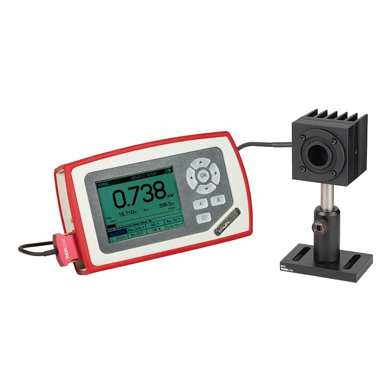
Power meters
For sporadic measurements outside the laser system (e.g. during maintenance) a separate measuring unit is beneficial. For such a power meter, the sensor element is usually integrated into a metal housing for mechanical and thermal stability. The signal is recorded and processed in a read-out unit which displays the measured laser power (Fig 8).[21]
Ultrafast laser measurement
Short-pulsed lasers which are used in spectroscopy and optical communication can be measured using thermopile sensors since they possess high thresholds for laser induced damages, especially when equipped with a volume absorber. (see section 2.5).
Position detector

An arrangement of several thermally coupled thermopile sensors similar to a quadrant photodiode design (Fig 9) can be used to detect beam position as well as beam power. This is useful for beam alignment purposes or for processes where a correct beam position is crucial for high production yield.[21]
Comparison between different types of detectors.
| Feature | Thermopile | Photodiode | Pyroelectric | Calorimeter |
|---|---|---|---|---|
| Physical principle | Thermoelectricity | Electrons hole combination | Pyro electricity | Thermoelectricity |
| Spectral Range | Broadband | narrow band | narrow band | broadband |
| Power Range | Low to medium | Low | Low to medium energies | Very high energies |
| Signal | Voltage(V) | Current(A) | Voltage(V) or Current(A) | Voltage(V) |
| Response time | High | Low | Low | High |
| Wavelength dependent sensitivity | No | Yes | No | No |
| Linear response | Yes | Yes, up to saturation | -- | -- |
| Effect of small variation of incident angle | Negligible | Significant | Negligible | Negligible |
References
- ^ "gRAY Sensors".
- ^ a b "Product Specification C-Series". Thorlabs. 6 May 2016. Retrieved 6 May 2016.
- ^ "Working Principle". gRAY. Retrieved 6 May 2016.
- ^ Bashar, Dr. Shabir A. (7 May 2016). "Study of Indium Tin Oxide (ITO) for Novel Optoelectronic Devices". Retrieved 7 May 2016.
- ^ "Throlabs C-Series Power Meter". 6 May 2016. Retrieved 6 May 2016.
- ^ J. Weidner (2009). Integrated Optoelectronics 4, Issue 41. The Electrochemical Society. ISBN 9781566777223.
- ^ a b c "Comparison of pyroelectric and thermopile", Norbert Neumann, Victor Banta, Infra Tec GmbH, Gostritzer Str.61-61, 01217 Dresden, Germany and Dexter Research Center, Inc., 7300 Huron River Drive, Dexter; MI 48130, USA
- ^ a b c d e f g h i j ʺReinventing Thermal Laser Power Measurementsʺ, Lasers in Manufacturing Conference 2015, S. Dröscher, M. Zahner, E. Schwyter, T. Helbling and C. Hierold
- ^ a b D. Pollock, Daniel (1985). Thermoelectricity: Theory, Thermometry, Tool, Issue 852. ASTM International. ISBN 9780803104099.
- ^ "gRAY Laser Power Detectors by greenTEG". gRAY - Laser Power Detectors. Retrieved 2016-04-28.
- ^ a b c d e f g "Thermopile Laser Power Sensor Technology Tutorial". www.newport.com. Retrieved 2016-04-28.
- ^ a b c d "Laser induced damage threshold". thorlabs.com.
- ^ a b c "Laser Induced Damage". RP Photonics.
- ^ "B01-SC". gRAY, greenTEG.
- ^ a b John H Lienhard (2019). A Heat Transfer Textbook: 5th Edition. Dover Pub.
- ^ Hugh H. Richardson, Michael T. Carlson, Peter J. Tandler, Pedro Hernandez, and Alexander O. Govorov (6 May 2016). "Experimental and theoretical studies of light-to-heat conversion and collective heating effects in metal nanoparticle solutions". Nano Lett. 9 (3): 1139–46. doi:10.1021/nl8036905. PMC 2669497. PMID 19193041.
{{cite journal}}: CS1 maint: multiple names: authors list (link) - ^ IUPAC, Compendium of Chemical Terminology, 2nd ed. (the "Gold Book") (1997). Online corrected version: (2006–) "Absorbance".
- ^ Kengo Kishimoto, Masayoshi Tsukamoto and Tsuyoshi Koyanagi (6 May 2016). "Temperature dependence of the Seebeck coefficient and the potential barrier scattering of n-type PbTe films prepared on heated glass substrates by rf sputtering". Journal of Applied Physics. 92 (9): 5331–5339. doi:10.1063/1.1512964.
- ^ a b "Thermal Management for Thermopile Laser Power Sensors" (PDF). gRAY. 6 May 2016. Retrieved 6 May 2016.
- ^ a b "Thermocouples: Theory". 6 May 2016. Retrieved 6 May 2016.
- ^ a b c d e f "Applications" (PDF). gray.greenteg.com. 2015-08-18.
- ^ "Thorlabs Power Meter". thorlabs.com.
- ^ "Position Sensor". gray.greenteg.com.
- ^ "Thermal sensor vs Photodiode" (PDF). gray.greenteg.com. 6 May 2016. Retrieved 6 May 2016.
- ^ Gentec EO Product Guide. gentec EO. 2014.
