


Informatics Educational Institutions & Programs

Induction plasma, also called inductively coupled plasma, is a type of high temperature plasma generated by electromagnetic induction, usually coupled with argon gas. The magnetic field induces an electric current within the gas which creates the plasma. The plasma can reach temperatures up to 10,000 Kelvin. Inductive plasma technology is used in fields such as powder spheroidization and nano-material synthesis. The technology is applied via an Induction plasma torch, which consists of three basic elements: the induction coil, a confinement chamber, and a torch head, or gas distributor. The main benefit of this technology is the elimination of electrodes, which can deteriorate and introduce contamination.
History
The 1960s were the incipient period of thermal plasma technology, spurred by the needs of aerospace programs. Among the various methods of thermal plasma generation, induction plasma (or inductively coupled plasma) takes up an important role.
Early attempts to maintain inductively coupled plasma on a stream of gas date back to Babat[1] in 1947 and Reed[2] in 1961. Effort was concentrated on the fundamental studies of energy coupling mechanism and the characteristics of the flow, temperature and concentration fields in plasma discharge. In the 1980s, there was increasing interest in high-performance materials and other scientific issues, and in induction plasma for industrial-scale applications such as waste treatment. Substantial research and development was devoted to bridge the gap between laboratory gadget and industry integration. After decades' effort, induction plasma technology has gained a firm foothold in modern advanced industry.
Generation
Induction heating is a mature technology with centuries of history. A conductive metallic piece, inside a coil of high frequency, will be "induced", and heated to the red-hot state. There is no difference in cardinal principle for either induction heating or "inductively coupled plasma", only that the medium to induce, in the latter case, is replaced by the flowing gas, and the temperature obtained is extremely high, as it arrives the "fourth state of matter"—plasma.

An inductively coupled plasma (ICP) torch is essentially a copper coil of several turns, through which cooling water is running in order to dissipate the heat produced in operation. The ICPs have two operation modes, called capacitive (E) mode with low plasma density and inductive (H) mode with high plasma density, and E to H heating mode transition occurs with external inputs.[3] The coil wraps a confinement tube, inside which the induction (H mode) plasma is generated. One end of the confinement tube is open; the plasma is actually maintained on a continuum gas flow. During induction plasma operation, the generator supplies an alternating current (ac) of radio frequency (r.f.) to the torch coil; this ac induces an alternating magnetic field inside the coil, after Ampère's law (for a solenoid coil):

where, is the flux of magnetic field, is permeability constant , is the coil current, is the number of coil turns per unit length, and is the mean radius of the coil turns.


According to Faraday's Law, a variation in magnetic field flux will induce a voltage, or electromagnetic force:

where, is the number of coil turns, and the item in parentheses is the rate at which the flux is changing. The plasma is conductive (assuming a plasma already exists in the torch). This electromagnetic force, E, will in turn drive a current of density j in closed loops. The situation is much similar to heating a metal rod in the induction coil: energy transferred to the plasma is dissipated via Joule heating, j2R, from Ohm's law, where R is the resistance of plasma.
Since the plasma has a relatively high electrical conductivity, it is difficult for the alternating magnetic field to penetrate it, especially at very high frequencies. This phenomenon is usually described as the "skin effect". The intuitive scenario is that the induced currents surrounding each magnetic line counteract each other, so that a net induced current is concentrated only near the periphery of plasma. It means the hottest part of plasma is off-axis. Therefore, the induction plasma is something like an "annular shell". Observing on the axis of plasma, it looks like a bright "bagel".

In practice, the ignition of plasma under low pressure conditions (<300 torr) is almost spontaneous, once the r.f. power imposed on the coil achieves a certain threshold value (depending on the torch configuration, gas flow rate etc.). The state of plasma gas (usually argon) will swiftly transit from glow-discharge to arc-break and create a stable induction plasma. For the case of atmospheric ambient pressure conditions, ignition is often accomplished with the aid of a Tesla coil, which produces high-frequency, high-voltage electric sparks that induce local arc-break inside the torch and stimulate a cascade of ionization of plasma gas, ultimately resulting in a stable plasma.
Induction plasma torch

Induction plasma torch is the core of the induction plasma technology. Despite the existence of hundreds of different designs, an induction plasma torch consists of essentially three components:
- Coil
- The induction coil consists of several spiral turns, depending on the r.f. power source characteristics. Coil parameters including the coil diameter, number of coil turns, and radius of each turn, are specified in such a way to create an electrical "tank circuit" with proper electrical impedance. Coils are typically hollow along their cylindrical axis, filled with internal liquid cooling (e.g., de-ionized water) to mitigate high operating temperatures of the coils that result from the high electrical currents required during operation.
- Confinement tube
- This tube serves to confine the plasma. Quartz tube is the common implementation. The tube is often cooled either by compressed air (<10 kW) or cooling water. While the transparency of quartz tube is demanded in many laboratory applications (such as spectrum diagnostic), its relatively poor mechanical and thermal properties pose a risk to other parts (e.g., o-ring seals) that may be damaged under the intense radiation of high-temperature plasma. These constraints limit the use of quartz tubes to low power torches only (<30 kW). For industrial, high power plasma applications (30~250 kW), tubes made of ceramic materials are typically used.[4] The ideal candidate material will possess good thermal conductivity and excellent thermal shock resistance. For the time being, silicon nitride (Si3N4) is the first choice. Torches of even greater power employ a metal wall cage for the plasma confinement tube, with engineering tradeoffs of lower power coupling efficiencies and increased risk of chemical interactions with the plasma gases.
- Gas distributor
- Often called a torch head, this part is responsible for the introduction of different gas streams into the discharge zone. Generally, there are three gas lines passing to the torch head. According to their distance to the center of circle, these three gas streams are also arbitrarily named as Q1, Q2, and Q3.
Q1 is the carrier gas that is usually introduced into the plasma torch through an injector at the center of the torch head. As the name indicates it, the function of Q1 is to convey the precursor (powders or liquid) into plasma. Argon is the usual carrier gas, however, many other reactive gases (i.e., oxygen, NH3, CH4, etc.) are often involved in the carrier gas, depending on the processing requirement.
Q2 is the plasma forming gas, commonly called as the "Central Gas". In today's induction plasma torch design, it is almost unexceptional that the central gas is introduced into the torch chamber by tangentially swirling. The swirling gas stream is maintained by an internal tube that hoops the swirl till to the level of the first turn of induction coil. All these engineering concepts are aiming to create the proper flow pattern necessary to insure the stability of the gas discharge in the center of the coil region.
Q3 is commonly referred to as "Sheath Gas" that is introduced outside the internal tube mentioned above. The flow pattern of Q3 can be either vortex or straight. The function of sheath gas is twofold. It helps to stabilize the plasma discharge; most importantly, it protects the confinement tube, as a cooling medium.
Plasma gases and plasma performance
The minimum power to sustain an induction plasma depends on pressure, frequency and gas composition. The lower sustaining power setting is achieved with high r.f. frequency, low pressure, and monatomic gas, such as argon. Once diatomic gas is introduced into the plasma, the sustaining power would be drastically increased, because extra dissociation energy is required to break gaseous molecular bonds first, so then further excitation to plasma state is possible. The major reasons to use diatomic gases in plasma processing are (1) to get a plasma of high energy content and good thermal conductivity (see Table below), and (2) to conform the processing chemistry.
| Gas | Specific gravity[a] |
Thermal dissociation energy (eV) |
Ionization energy (eV) |
Thermal conductivity[b] (W/m·K) |
Enthalpy[b] (MJ/mol) |
|---|---|---|---|---|---|
| Ar | 1.380 | — | 15.76 | 0.644 | 0.24 |
| He | 0.138 | — | 24.28 | 2.453 | 0.21 |
| H2 | 0.069 | 4.59 | 13.69 | 3.736 | 0.91 |
| N2 | 0.967 | 9.76 | 14.53 | 1.675 | 1.49 |
| O2 | 1.105 | 5.17 | 13.62 | 1.370 | 0.99 |
| Air | 1.000 | — | — | 1.709 | 1.39 |
In practice, the selection of plasma gases in an induction plasma processing is first determined by the processing chemistry, i.e., if the processing requiring a reductive or oxidative, or other environment. Then suitable second gas may be selected and added to argon, so as to get a better heat transfer between plasma and the materials to treat. Ar–He, Ar–H2, Ar–N2, Ar–O2, air, etc. mixture are very commonly used induction plasmas. Since the energy dissipation in the discharge takes places essentially in the outer annular shell of plasma, the second gas is usually introduced along with the sheath gas line, rather than the central gas line.
Industrial application of induction plasma technology
Following the evolution of the induction plasma technology in laboratories, the major advantages of the induction plasma have been identified:
- Induction plasma allows to create a high purity plasma without contamination from electrodes as it is the case in DC plasma.
- The possibility of the axial feeding of precursors, being solid powders, or suspensions, liquids. This feature allows to expose materials to the high temperature of plasma of up to 10000 °C.
- Due to the absence of electrodes, a wide selection of process gases is possible, i.e., the torch could work in either reductive, or, oxidative, even corrosive atmospheres. With this capability, an induction plasma torch often works as not only a high temperature, high enthalpy heat source, but also chemical reaction vessels.
- Relatively long residence time of precursor in the plasma plume (several milliseconds up to hundreds milliseconds), compared with dc plasma.
- Relatively large plasma volume.
These features of induction plasma technology, has found niche applications in industrial scale operation in the last decade. The successful industrial application of induction plasma process depends largely on many fundamental engineering supports. For example, the industrial plasma torch design, which allows high power level (50 to 600 kW) and long duration (three shifts of 8 hours/day) of plasma processing. Another example is the powder feeders that convey large quantity of solid precursor (1 to 30 kg/h) with reliable and constant feed rate.
There are many examples of the industrial applications of induction plasma technology, such as powder spheroidization, nanosized powders synthesis, induction plasma spraying, waste treatments.[5][6]
Powder spheroidization

Source:[7]
The requirement of powders spheroidization (as well as densification) comes from very different industrial fields, from powder metallurgy to the electronic packaging. Generally speaking, the pressing need for an industrial process to turn to spherical powders is to seek at least one of the following benefits which result from the spheroidization process:
- Improve the powders flow-ability.
- Increase the powders packing density.
- Eliminate powder internal cavities and fractures.
- Change the surface morphology of the particles.
- Other unique motive, such as optical reflection, chemical purity etc.
spheroidization is a process of in-flight melting. The powder precursor of angular shape is introduced into induction plasma, and melted immediately in the high temperatures of plasma. The melted powder particles are assuming the spherical shape under the action of surface tension of liquid state. These droplets will be drastically cooled down when fly out of the plasma plume, because of the big temperature gradient exciting in the plasma. The solidified spheres are thus collected as the spheroidization products. As the process does not use any electrodes or crucibles a very high purity can be maintained.
A great variety of ceramics, metals and metal alloys have been successfully spheroidized/densified using induction plasma spheroidization. Due to the high temperature of the plasma even materials with very high melting temperatures can be spheroidized. Following are some typical materials that are spheroidized on a commercial scale.
- Oxide ceramics: SiO2, ZrO2, YSZ, Al2TiO5, glass
- Non-oxides: WC, WC–Co, CaF2, TiN
- Metals: Re, Ta, Mo, W
- Alloys: Cr–Fe–C, Re–Mo, Re–W
Nano-materials synthesis
It is the increased demand for nanopowders that promotes the extensive research and development of various techniques for the synthesis of nanometric powders. The challenges for an industrial application technology are productivity, quality controllability, and affordability. Induction plasma technology implements in-flight evaporation of precursor, even those raw materials of the highest boiling point; operating under various atmospheres, permitting synthesis of a great variety of nanopowders, and thus become much more reliable and efficient technology for synthesis of nanopowders in both laboratory and industrial scales. Induction plasma used for nanopowder synthesis has many advantages over the alternative techniques, such as high purity, high flexibility, easy to scale up, easy to operate and process control.
In the nano-synthesis process, material is first heated up to evaporation in induction plasma, and the vapours are subsequently subjected to a very rapid quenching in the quench/reaction zone. The quench gas can be inert gases such as Ar and N2 or reactive gases such as CH4 and NH3, depending on the type of nanopowders to be synthesized. The nanometric powders produced are usually collected by porous filters, which are installed away from the plasma reactor section. Because of the high reactivity of metal powders, special attention should be given to powder pacification prior to the removal of the collected powder from the filtration section of the process.
The induction plasma system has been successfully used in the synthesis of nanopowders. The typical size range of the nano-particles produced is from 20 to 100 nm, depending on the quench conditions employed. The productivity varies from few hundreds g/h to 3~4 kg/h, according to the different materials' physical properties and the power level of the plasma. A typical induction plasma nano-synthesis system for industrial application is shown below. The photos of some nano-product from the same equipment are included.
Plasma wind tunnels
During atmosperic entry space crafts are exposed to high heat fluxes and need to be protected with thermal protection systems materials. For the development these materials need to be tested in similar conditions. Plasma wind tunnels also called high enthalpy ground testing facilities reproduce these conditions. Induction plasma is used for these plasma wind tunnels because it can generate a high-enthalpy plasma free of contaminants. [8]
Gallery
-
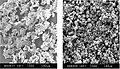 The flaky interlocking rhenium powders become dense separate spheres after the induction plasma spheroidization processing
 -
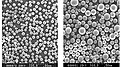 The SiO2 powder spheroidised by induction plasma (air plasma), output 15~20 kg/h
 -
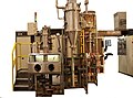 The induction plasma installation for nanopowders synthesis
 -
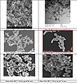 Some samples of the nanoparticles prepared by induction plasma processing


Summary
Induction plasma technology achieves mainly the aforementioned high-added-value processes. Besides the "spheroidization" and "nanomaterial synthesis", the high risk waste treatment, refractory materials deposit, noble material synthesis etc. may be the next industrial fields for induction plasma technology.
See also
Notes
References
- ^ Babat, George I. (1947). "Electrodeless discharges and some allied problems". Journal of the Institution of Electrical Engineers - Part III: Radio and Communication Engineering. 94 (27): 27–37. doi:10.1049/ji-3-2.1947.0005.
- ^ Reed, Thomas B. (1961). "Induction‐Coupled Plasma Torch". Journal of Applied Physics. 32 (5): 821–824. Bibcode:1961JAP....32..821R. doi:10.1063/1.1736112.
- ^ Hyo-Chang Lee (2018) Review of inductively coupled plasmas: Nano-applications and bistable hysteresis physics 5 011108 https://doi.org/10.1063/1.5012001
- ^ United States Patent 5200595
- ^ M. I. Boulos, "Radio frequency plasma developments, scale-up and industrial applications", Journal of High Temperature Chemical Processes, 1(1992)401–411
- ^ M. I. Boulos, "The Inductively Coupled Radio Frequency Plasma", High Temperature Material Processes: An International Quarterly of High-Technology Plasma Processes, 1(1997)17–39
- ^ M. I. Boulos, "Plasma power can make better powders", Metalpowder Report, No. 5, (2004)16–21
- ^ Sirmalla, Prathamesh R.; Munafò, Alessandro; Kumar, Sanjeev; Bodony, Daniel J.; Panesi, Marco (2024-01-04). "Modeling the plasma jet in the Plasmatron X ICP facility". AIAA SCITECH 2024 Forum. Reston, Virginia: American Institute of Aeronautics and Astronautics. doi:10.2514/6.2024-1685.
