Informatics Educational Institutions & Programs
Contents
In electronics and telecommunications, pulse shaping is the process of changing a transmitted pulses' waveform to optimize the signal for its intended purpose or the communication channel. This is often done by limiting the bandwidth of the transmission and filtering the pulses to control intersymbol interference. Pulse shaping is particularly important in RF communication for fitting the signal within a certain frequency band and is typically applied after line coding and modulation.
Need for pulse shaping
Transmitting a signal at high modulation rate through a band-limited channel can create intersymbol interference. The reason for this are Fourier correspondences (see Fourier transform). A bandlimited signal corresponds to an infinite time signal, that causes neighbouring pulses to overlap. As the modulation rate increases, the signal's bandwidth increases.[1] As soon as the spectrum of the signal is a sharp rectangular, this leads to a sinc shape in the time domain. This happens if the bandwidth of the signal is larger than the channel bandwidth, leading to a distortion. This distortion usually manifests itself as intersymbol interference (ISI). Theoretically for sinc shaped pulses, there is no ISI, if neighbouring pulses are perfectly aligned, i.e. in the zero crossings of each other. But this requires a very good synchronization and precise/stable sampling without jitters. As a practical tool to determine ISI, one uses the Eye pattern, that visualizes typical effects of the channel and the synchronization/frequency stability.
The signal's spectrum is determined by the modulation scheme and data rate used by the transmitter, but can be modified with a pulse shaping filter. This pulse shaping will make the spectrum smooth, leading to a time limited signal again. Usually the transmitted symbols are represented as a time sequence of dirac delta pulses multiplied with the symbol. This is the formal transition from the digital to the analog domain. At this point, the bandwidth of the signal is unlimited. This theoretical signal is then filtered with the pulse shaping filter, producing the transmitted signal. If the pulse shaping filter is a rectangular in the time domain (like this is usually done when drawing it), this would lead to an unlimited spectrum.
In many base band communication systems the pulse shaping filter is implicitly a boxcar filter. Its Fourier transform is of the form sin(x)/x, and has significant signal power at frequencies higher than symbol rate. This is not a big problem when optical fibre or even twisted pair cable is used as the communication channel. However, in RF communications this would waste bandwidth, and only tightly specified frequency bands are used for single transmissions. In other words, the channel for the signal is band-limited. Therefore, better filters have been developed, which attempt to minimise the bandwidth needed for a certain symbol rate.
An example in other areas of electronics is the generation of pulses where the rise time need to be short; one way to do this is to start with a slower-rising pulse, and decrease the rise time, for example with a step recovery diode circuit.
These descriptions here provide a working knowledge, that cover most effects, but do not include causality, which would lead to analytical functions/signals. To understand this completely, one needs the Hilbert transform, that induces a direction by the convolution with the Cauchy Kernel. This couples the real and imaginary part of the baseband description, thereby adding structure. This immediately implies, that either the real or the imaginary part are enough to describe an analytical signal. By measuring both in a noisy setting, one has a redundancy, that can be used to better reconstruct the original signal. A physical realization is always causal, since an analytic signal carries the information.
Pulse shaping filters

Not every filter can be used as a pulse shaping filter. The filter itself must not introduce intersymbol interference — it needs to satisfy certain criteria. The Nyquist ISI criterion is a commonly used criterion for evaluation, because it relates the frequency spectrum of the transmitter signal to intersymbol interference.
Examples of pulse shaping filters that are commonly found in communication systems are:
- Sinc shaped filter
- Raised-cosine filter
- Gaussian filter
Sender side pulse shaping is often combined with a receiver side matched filter to achieve optimum tolerance for noise in the system. In this case the pulse shaping is equally distributed between the sender and receiver filters. The filters' amplitude responses are thus pointwise square roots of the system filters.
Other approaches that eliminate complex pulse shaping filters have been invented. In OFDM, the carriers are modulated so slowly that each carrier is virtually unaffected by the bandwidth limitation of the channel.
Sinc filter

It is also called as Boxcar filter as its frequency domain equivalent is a rectangular shape. Theoretically the best pulse shaping filter would be the sinc filter, but it cannot be implemented precisely. It is a non-causal filter with relatively slowly decaying tails. It is also problematic from a synchronisation point of view as any phase error results in steeply increasing intersymbol interference.
Raised-cosine filter
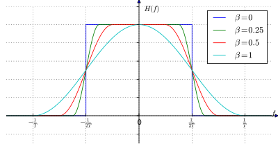
Raised-cosine is similar to sinc, with the tradeoff of smaller sidelobes for a slightly larger spectral width. Raised-cosine filters are practical to implement and they are in wide use. They have a configurable excess bandwidth, so communication systems can choose a trade off between a simpler filter and spectral efficiency.
Gaussian filter
This gives an output pulse shaped like a Gaussian function.
See also
- Nyquist ISI criterion
- Raised-cosine filter
- Matched filter
- Femtosecond pulse shaping
- Pulse (signal processing)
References
- John G. Proakis, "Digital Communications, 3rd Edition" Chapter 9, McGraw-Hill Book Co., 1995. ISBN 0-07-113814-5
- National Instruments Signal Generator Tutorial, Pulse Shaping to Improve Spectral Efficiency
- National Instruments Measurement Fundamentals Tutorial, Pulse-Shape Filtering in Communications Systems
- Root Raised Cosine Filters & Pulse Shaping in Communication Systems by Erkin Cubukcu (ntrs.nasa.gov).


